
 车间信息采集与控制
# Smart之车间信息采集与控制
# 1. 说明
本范例采用MQTT通讯协议,采集源于设备的数据信息,通过MQTT向指定主题发布信息,接收端接收信息并显示。
在生产车间中,我们会关心车间设备的运行参数以及车间的环境情况,这样就可以及时了解车间设备的运行情况以及车间的运行情况,然后及时做出相关预警信息。本硬件设备范例使用I2C,ModbusRTU,模拟针脚线等采集连接的硬件的采集数据信息,然后通过MQTT协议来传输信息,在MQTT客户端上连接到中间件,订阅Motor/#主题就可获取到采集的所有数据信息。
通过本范例学习,可以掌握MQTT的基本通讯原理,并结合Arduino开发板实现数据采集显示和控制的功能。
# 2. 零件连接图
本示例由于线路连接较为复杂,连线图可能无法清晰展示实际的连接情况,此处将各个硬件的连接使用表格进行罗列。
将使用的传感器及相关硬件分别连接至Arduino Mega2560,首先将W5100网络扩展板接入Arduino Mega2560并通过网线连接至局域网中,然后按照下方的表格列出的接口进行对照连接。其中继电器的COM、NO端需串联接入至电动机的交流电路中。
| 噪声传感器 | Arduino Mega2560 | |
|---|---|---|
| 5V | -> | 5V |
| GND | -> | GND |
| TXD | -> | RX1 |
| RXD | -> | TX1 |
| 功率因数盒 | TTL-RS485转换器 | |
|---|---|---|
| A | -> | A |
| B | -> | B |
| TTL-RS485转换器 | Arduino Mega2560 | |
|---|---|---|
| VCC | -> | 5V |
| GND | -> | GND |
| TXD | -> | RX2 |
| RXD | -> | TX2 |
| PT100 | MAX31865 | |
|---|---|---|
| red1 or red2 | -> | RTD+ |
| red2 or red1 | -> | F+ |
| white | -> | F- or RTD- |
| MAX31865 | Arduino Mega2560 | |
|---|---|---|
| VCC | -> | 5V |
| GND | -> | GND |
| CLK | -> | 13 |
| SDO | -> | 12 |
| SDI | -> | 11 |
| CS | -> | 10 |
| BH1750 | Arduino Mega2560 | |
|---|---|---|
| VCC | -> | 5V |
| GND | -> | GND |
| SCL | -> | SCL |
| SDA | -> | SDA |
| 霍尔传感器 | Arduino Mega2560 | |
|---|---|---|
| VCC | -> | 5V |
| GND | -> | GND |
| D0 | 2 |
| 压电陶瓷振动传感器 | Arduino Mega2560 | |
|---|---|---|
| + | -> | 5V |
| - | -> | GND |
| S | -> | A0 |
| 夏普GP2Y1010AU0F粉尘传感器 | Arduino Mega2560 | |
|---|---|---|
| 1 | -> | 5V(两者间串联150Ω电阻,pin 1和电阻之间并联220μF电容 电容长脚端与pin1相连,短脚端接至Arduino GND脚) |
| 2 | -> | GND |
| 3 | -> | 7 |
| 4 | -> | GND |
| 5 | -> | A1 |
| 6 | -> | 5V |
| MQ135 | Arduino Mega2560 | |
|---|---|---|
| VCC | -> | 5V |
| AOUT | -> | A2 |
| GND | -> | GND |
| DHT11 | Arduino Mega2560 | |
|---|---|---|
| + | -> | 5V |
| - | -> | GND |
| OUT | -> | 8 |
| 继电器 | Arduino Mega2560 | |
|---|---|---|
| DC+ | -> | 5V |
| DC- | -> | GND |
| IN | -> | 9 |
# 3. 使用零件
| 序号 | 硬件名称 | 数量 |
|---|---|---|
| 1 | Arduino Mega 2560开发板 | 1 |
| 2 | W5100网络扩展板 | 1 |
| 3 | peacefair PZEM-016功率因数检测盒(ModbusRTU通信) | 1 |
| 4 | 噪声传感器(TTL接口) | 1 |
| 5 | PT100贴片式热电阻传感器(三线) | 1 |
| 6 | MAX31865 RTD至数字输出转换器 | 1 |
| 7 | BH1750光线传感器 | 1 |
| 8 | 霍尔传感器测速模块 | 1 |
| 9 | 铷铁硼磁铁块 | 1 |
| 10 | 模拟压电陶瓷震动传感器(带压电陶瓷) | 1 |
| 11 | DHT11温湿度传感器 | 1 |
| 12 | MQ-135空气质量传感器 | 1 |
| 13 | 夏普GP2Y1014AU粉尘传感器(附带150Ω电阻以及220μF电解电容器) | 1 |
| 14 | 插排(无线) | 1 |
| 15 | TTL转RS485转换器(具有TX、RX针脚的类型) | 1 |
| 16 | 插头(无线) | 1 |
| 17 | RV1.5线缆2米,三种不同颜色 | 1 |
| 18 | 单路继电器 | 1 |
| 19 | 220V电动机 | 1 |
| 20 | 杜邦线 | 若干 |
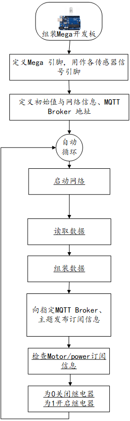
# 4. Arduino流程图
# 5. Arduino程序
使用Arduino IDE 编译并上传以下Arduino程序。使用该程序需导入ModbusMaster、Adafruit_MAX31865、DHT、PubSubClient等相关库。
#include <ModbusMaster.h>
#include <SoftwareSerial.h>
#include <Adafruit_MAX31865.h>
#include <Wire.h> //BH1750 IIC Mode
#include <math.h>
#include <DHT.h>
#include <SPI.h>
#include <Ethernet.h>
#include <PubSubClient.h>
// MQTT 宣告 ========================================================


EthernetClient ethClient;
PubSubClient client(ethClient);

#define dhtPin 8                    //读取DHT11 Data
#define POWERPIN 9                  //设置电源信号输出针脚
#define dhtType DHT11               //选用DHT11

#define STRING_LEN 128

DHT dht(dhtPin, dhtType); // Initialize DHT sensor


const String MQTTClientName = "Motor";        //定义MQTT客户端名称

char Topic[100];    //设置主题变量


// 设置网络IP地址 (网络扩充卡 MAC 可自行修改 +1 避免冲突)
byte mac[] = {0x90, 0xA2, 0xDA, 0x0E, 0x94, 0xA3 };
IPAddress ip(192, 168, 0, 234);
IPAddress gateway(192, 168, 0, 1);
IPAddress subnet(255, 255, 255, 0);

// Use software SPI: CS, DI, DO, CLK
Adafruit_MAX31865 thermo = Adafruit_MAX31865(10, 11, 12, 13);

// The value of the Rref resistor. Use 430.0 for PT100 and 4300.0 for PT1000
#define RREF      430.0
// The 'nominal' 0-degrees-C resistance of the sensor
// 100.0 for PT100, 1000.0 for PT1000
#define RNOMINAL  100.0

//噪声传感器TTL-> Serial1
//const int SSRxPin = 6; // Recieve pin for software serial (Rx on RS485 adapter)
//const int SSTxPin = 7; // Send pin for software serial (Tx on RS485 adapter)
//SoftwareSerial modbusNoiseSerial(SSRxPin, SSTxPin);

//电能传感器TTL->Serial2

//const int SSRxEPin = 4; // Recieve pin for software serial (Rx on RS485 adapter)
//const int SSTxEPin = 5; // Send pin for software serial (Tx on RS485 adapter)
//SoftwareSerial modbusElectricSerial(SSRxEPin, SSTxEPin);


// instantiate ModbusMaster object
ModbusMaster nodeNoise;
ModbusMaster nodeElectric;

int BH1750address = 0x23; //setting i2c address
byte buff[2];

int Rotationpin = 2; //定义霍尔计数器的引脚为D2
unsigned long duration=0; //定义duration变量为无符号长整数型变量
int i = 0;

//粉尘传感器变量
#define measurePin A1//输出引脚连接模拟口A1
#define ledPin 7 //LED引脚连接数字口9
unsigned int samplingTime = 280;//根据前面分析采样时间为280,所以这里为280
unsigned int deltaTime = 40;//测量完后脉冲需要继续保持,保持时间为320-280=40
unsigned int sleepTime = 9680;//LED脉冲周期为10毫秒,故此处为10000-320=9680
float voMeasured = 0;
float calcVoltage = 0;
float dustDensity = 0;

//MQ135 变量初始设置 针脚为A2
const int gasSensor =2;


//噪声传感器初始化
void noiseSetup(){

  // initialize Modbus communication baud rate
  Serial1.begin(9600);
  // communicate with Modbus slave ID 1 over Soft Serial
  nodeNoise.begin(1, Serial1);
}

//噪声传感器读取数据
void noiseRead(){
  uint8_t j, result;
  uint16_t data;

  // set word 0 of TX buffer to least-significant word of counter (bits 15..0)
  //node.setTransmitBuffer(0, lowWord(i));

  // set word 1 of TX buffer to most-significant word of counter (bits 31..16)
  //node.setTransmitBuffer(1, highWord(i));

  // slave: write TX buffer to (2) 16-bit registers starting at register 0
  //result = node.writeMultipleRegisters(0, 2);

  // slave: read (6) 16-bit registers starting at register 2 to RX buffer
  result = nodeNoise.readHoldingRegisters(0, 1);

  // do something with data if read is successful
  if (result == nodeNoise.ku8MBSuccess)
  {
      Serial.println("Noise Sensor Via ModbusRTU");
      data = nodeNoise.getResponseBuffer(0);
      Serial.print(data * 0.1);
      Serial.println("dB");

      //发布主题
      char noise[20];
      dtostrf(data * 0.1,3,1,noise);
      String NoiseTopic = MQTTClientName + "/noise";
      NoiseTopic.toCharArray(Topic,100);
      client.publish(Topic, noise);
  }
}


//电能传感器初始化
void ElectricSetup(){
  // initialize Modbus communication baud rate
  Serial2.begin(9600);
  // communicate with Modbus slave ID 1 over Soft Serial
  nodeElectric.begin(1, Serial2);
}

void ElectricRead(){
  static uint32_t i;
  uint8_t j, result;
  uint16_t data[10];

  //i++;

  // set word 0 of TX buffer to least-significant word of counter (bits 15..0)
  //node.setTransmitBuffer(0, lowWord(i));

  // set word 1 of TX buffer to most-significant word of counter (bits 31..16)
  //node.setTransmitBuffer(1, highWord(i));

  // slave: write TX buffer to (2) 16-bit registers starting at register 0
  //result = node.writeMultipleRegisters(0, 2);

  // slave: read (6) 16-bit registers starting at register 2 to RX buffer
  //result = node.readHoldingRegisters(0, 5);
    result = nodeElectric.readInputRegisters(0,9);

  // do something with data if read is successful
  if (result == nodeElectric.ku8MBSuccess)
  {
    for (j = 0; j < 9; j++)
    {
      data[j] = nodeElectric.getResponseBuffer(j);
      //Serial.println(data[j] * 0.1);

    }
    //电压值
    Serial.print("U:");
    Serial.print(data[0] * 0.1);
    Serial.println("V");

    char voltage[20];
    dtostrf(data[0] * 0.1,3,1,voltage);
    String voltageTopic = MQTTClientName + "/voltage";
    voltageTopic.toCharArray(Topic,100);
    client.publish(Topic, voltage);

    //电流测量
    Serial.print("I:");
    Serial.print((data[2] * 65536 + data[1]) * 0.001);
    Serial.println("A");

    char current[20];
    dtostrf((data[2] * 65536 + data[1]) * 0.001,3,3,current);
    String currentTopic = MQTTClientName + "/current";
    currentTopic.toCharArray(Topic,100);
    client.publish(Topic, current);

    //功率测量
    Serial.print("P:");
    Serial.print((data[4] * 65536 + data[3]) * 0.1);
    Serial.println("W");

    //电能测量
    Serial.print("E:");
    Serial.print((data[6] * 65536 + data[5]) * 1);
    Serial.println("Wh");

  }
}


//MAX31865传感器初始化
void MAX31865Setup() {
  thermo.begin(MAX31865_3WIRE);  // set to 2WIRE or 4WIRE as necessary
}

//MAX31865读取温度
void MAX31865Read() {
  uint16_t rtd = thermo.readRTD();
  Serial.println("Adafruit MAX31865 PT100 Sensor Test!");

  Serial.print("RTD value: "); Serial.println(rtd);
  float ratio = rtd;
  ratio /= 32768;
  Serial.print("Ratio = "); Serial.println(ratio,8);
  Serial.print("Resistance = "); Serial.println(RREF*ratio,8);
  Serial.print("Temperature = "); Serial.println(thermo.temperature(RNOMINAL, RREF));

  char surftemp[20];
  dtostrf(thermo.temperature(RNOMINAL, RREF),3,2,surftemp);
  String surftempTopic = MQTTClientName + "/surftemp";
  surftempTopic.toCharArray(Topic,100);
  client.publish(Topic, surftemp);

  // Check and print any faults
  uint8_t fault = thermo.readFault();
  if (fault) {
    Serial.print("Fault 0x"); Serial.println(fault, HEX);
    if (fault & MAX31865_FAULT_HIGHTHRESH) {
      Serial.println("RTD High Threshold");
    }
    if (fault & MAX31865_FAULT_LOWTHRESH) {
      Serial.println("RTD Low Threshold");
    }
    if (fault & MAX31865_FAULT_REFINLOW) {
      Serial.println("REFIN- > 0.85 x Bias");
    }
    if (fault & MAX31865_FAULT_REFINHIGH) {
      Serial.println("REFIN- < 0.85 x Bias - FORCE- open");
    }
    if (fault & MAX31865_FAULT_RTDINLOW) {
      Serial.println("RTDIN- < 0.85 x Bias - FORCE- open");
    }
    if (fault & MAX31865_FAULT_OVUV) {
      Serial.println("Under/Over voltage");
    }
    thermo.clearFault();
  }
  Serial.println();
}

//BH1750设置
void BH1750Setup() {
  Wire.begin();
}

//BH1750 读取
int BH1750_Read(int address) //
{
  int i=0;
  Wire.beginTransmission(address);
  Wire.requestFrom(address, 2);
  while(Wire.available()) //
  {
    buff[i] = Wire.read();  // receive one byte
    i++;
  }
  Wire.endTransmission();
  return i;
}

//BH1750初始化
void BH1750_Init(int address)
{
  Wire.beginTransmission(address);
  Wire.write(0x10);//1lx reolution 120ms
  Wire.endTransmission();
}


//BH1750循环代码
void BH1750_Loop() {
  int i;
  uint16_t val=0;
  BH1750_Init(BH1750address);
  delay(200);

  if(2==BH1750_Read(BH1750address))
  {
    Serial.println("---BH1750 Light Sensor---");
    val=((buff[0]<<8)|buff[1])/1.2;
    Serial.print(val,DEC);
    Serial.println("[lx]");

    //发布亮度订阅
    char light[20];
    itoa(val,light,DEC);
    String lightTopic = MQTTClientName + "/light";
    lightTopic.toCharArray(Topic,100);
    client.publish(Topic, light);
  }
}

//读取振动数据
void viberateRead() {
    int val;
    Serial.println("---Viberation Sensor----");
    val=analogRead(0);      //将模拟压电陶瓷震动传感器连接到模拟接口0
    Serial.print("Vibration is ");
    Serial.println(val,DEC);//通过串口打印读取到的模拟值

    //发布振动压感数据
    char viberate[20];
    itoa(val,viberate,DEC);
    String viberateTopic = MQTTClientName + "/viberate";
    viberateTopic.toCharArray(Topic,100);
    client.publish(Topic, viberate);

}

//初始化设置计数引脚
void rotationSetup() {
  pinMode(Rotationpin, INPUT); //设置引脚为输入模式
}

//读取转速
void rotationRead() {
    duration=0;
    for(i=0;i<5;i++){
        duration += pulseIn(Rotationpin, HIGH);
        duration += pulseIn(Rotationpin, LOW);
    }
    Serial.println("Rotation Calculator");
    Serial.println(duration);
    duration = duration/5;
    Serial.println(duration);
    duration=1000000/duration;
    Serial.print(" f is ");
    Serial.print(duration);
    Serial.println(" HZ");
    duration = duration*60;
    Serial.print(" v is ");
    Serial.print(duration);
    Serial.println(" r/min");

    char rotation[20];
    itoa(duration,rotation,DEC);
    String rotationTopic = MQTTClientName + "/rotation";
    rotationTopic.toCharArray(Topic,100);
    client.publish(Topic, rotation);
}

//粉尘传感器初始化
void dustSetup() {
    pinMode(ledPin, OUTPUT);
    pinMode(A1, INPUT);
}

//粉尘传感器读取
void dustRead() {
    Serial.println("Dust Sensor");
    digitalWrite(ledPin, LOW);

    delayMicroseconds(samplingTime);
    voMeasured = analogRead(measurePin);

    delayMicroseconds(deltaTime);
    digitalWrite(ledPin, HIGH);

    delayMicroseconds(sleepTime);
    calcVoltage = voMeasured * (5.0 / 1024);
    dustDensity = 5000*calcVoltage/29 - 3000/29;

    if (dustDensity < 0) {
        dustDensity = 0.00;
    }
    Serial.print(dustDensity);
    Serial.print("μg/m3\n");

    char dust[20];
    dtostrf(dustDensity,10,2,dust);
    String dustTopic = MQTTClientName + "/dust";
    dustTopic.toCharArray(Topic,100);
    client.publish(Topic, dust);

}

//读取MQ135
void MQ135Read() {
  float voltage;
  voltage = getVoltage(gasSensor);

  Serial.println(voltage);

  char AQI[20];
  dtostrf(voltage,6,10,AQI);
  String AQITopic = MQTTClientName + "/AQI";
  AQITopic.toCharArray(Topic,100);
  client.publish(Topic, AQI);
}

float getVoltage(int pin){
  return (analogRead(pin) * 0.004882814);
  // This equation converts the 0 to 1023 value that analogRead()
  // returns, into a 0.0 to 5.0 value that is the true voltage
  // being read at that pin.
}

void DHTSetup() {
  dht.begin();//启动DHT
}

void DHTRead() {
  Serial.println("DHT Sensor");
   float h = dht.readHumidity();   //读取湿度
   float t = dht.readTemperature(); //读取摄氏温度
   if (isnan(h) || isnan(t)) {
     Serial.println("无法从DHT传感器读取!");
     return;
   }

//温度经由端口传出,字尾加 0x13
   Serial.print(t);
   Serial.println("℃");
   //Serial.write( 0x13 );
 // delay(500);
 //湿度经由端口传出,字尾加 0x66
   Serial.print(h);
   Serial.println("%RH");
   //Serial.write( 0x66 );

  char tmp[20];
  char hum[20];
  dtostrf(t,3,2,tmp);
  dtostrf(h,3,2,hum);
  String tmpTopic = MQTTClientName + "/tmp";
  String humTopic = MQTTClientName + "/hum";
  tmpTopic.toCharArray(Topic,100);
  client.publish(Topic, tmp);
  humTopic.toCharArray(Topic,100);
  client.publish(Topic, hum);
}


// 接收MQTT主题后调用运行程序
void callback(char* topic, byte* payload, unsigned int length) {
  String mapre01;                                       // 预定接收的主题1     /power
  String mapres;                                        // 实际从 MQTT Broker 接收到的主题
  String information;                                   // 实际从 MQTT Broker 接收到的主题内容
  String LEDOpen="1";
  //将 char[] 转为 String charToStringL(需转换的 Char阵列, 转换后的 String)

  mapre01 = "Motor/power";                                      //电源 的主題
  charToStringL(topic, mapres);                         //实际从 MQTT Broker 接收到的主题
  for (int i = 0; i < length; i++) {                    //转换 MQTT Broker 接收到的主题内容为字串
    information = information + (char)payload[i];
  }
  if (mapres != mapre01) {                              // 不显示发布的主题
     Serial.print("接收讯息 " + mapres + " [");
     Serial.print(information);
     Serial.print("] ");
  }

  if (mapres == mapre01) {
    if (information == LEDOpen) {
      Serial.println("打开 LED");
      digitalWrite(POWERPIN, HIGH);                      //PIN 8输出高电平,LED点亮
    }
    else {
      Serial.println("关闭 LED");
      digitalWrite(POWERPIN, LOW);                       //PIN 8输出低电平,LED熄灭
    }
  }
  delay(500);                                           //延时500ms
  Serial.println();
}

//将 char[] 转为 String 自定函数
void charToStringL(const char S[], String & D)
{
  byte at = 0;
  const char *p = S;
  D = "";

  while (*p++) {
    D.concat(S[at++]);
  }
}

void setup() {
  // put your setup code here, to run once:
  Serial.begin(9600);


   //设置 MQTT ========================================================
   client.setServer("192.168.0.113", 1883);                 // 连接 MQTT Broker
   client.setCallback(callback);                             // 设置从 MQTT Broker读取主题之后,自动运行之副程序

   Ethernet.begin(mac, ip, gateway, subnet);               // 启动网络
   Serial.println("网络已经开通");


   delay(1500);
   pinMode(POWERPIN, OUTPUT);                         // 设定脚位 PIN 6为输出模式
   noiseSetup();
   ElectricSetup();
   MAX31865Setup();
   BH1750Setup();
   rotationSetup();
   dustSetup();
   DHTSetup();
}

void loop() {
  // put your main code here, to run repeatedly:
  if (!client.connected()) {                              // 如果未联机 MQTT Broker 将重新联机
     reconnect();
  }
   client.loop();

  noiseRead();
  ElectricRead();
  MAX31865Read();
  BH1750_Loop();
  viberateRead();
  rotationRead();
  dustRead();
  MQ135Read();
  DHTRead();

  delay(2000);
}


void reconnect() {
  // 一直循环直到连上 MQTT Broker
  char MQTTClient[30];
  MQTTClientName.toCharArray(MQTTClient,30);
  while (!client.connected()) {
    Serial.print("正在连接 MQTT Broker...");
    if (client.connect(MQTTClient,"demo","123456")) {
      Serial.println("MQTT Broker 已经连接上");
      client.subscribe("Motor/power");
    } else {
      Serial.print("联机失败, rc=");
      Serial.print(client.state());
      Serial.println("五秒钟之后再联机");
      delay(5000);
    }
  }
}
2
3
4
5
6
7
8
9
10
11
12
13
14
15
16
17
18
19
20
21
22
23
24
25
26
27
28
29
30
31
32
33
34
35
36
37
38
39
40
41
42
43
44
45
46
47
48
49
50
51
52
53
54
55
56
57
58
59
60
61
62
63
64
65
66
67
68
69
70
71
72
73
74
75
76
77
78
79
80
81
82
83
84
85
86
87
88
89
90
91
92
93
94
95
96
97
98
99
100
101
102
103
104
105
106
107
108
109
110
111
112
113
114
115
116
117
118
119
120
121
122
123
124
125
126
127
128
129
130
131
132
133
134
135
136
137
138
139
140
141
142
143
144
145
146
147
148
149
150
151
152
153
154
155
156
157
158
159
160
161
162
163
164
165
166
167
168
169
170
171
172
173
174
175
176
177
178
179
180
181
182
183
184
185
186
187
188
189
190
191
192
193
194
195
196
197
198
199
200
201
202
203
204
205
206
207
208
209
210
211
212
213
214
215
216
217
218
219
220
221
222
223
224
225
226
227
228
229
230
231
232
233
234
235
236
237
238
239
240
241
242
243
244
245
246
247
248
249
250
251
252
253
254
255
256
257
258
259
260
261
262
263
264
265
266
267
268
269
270
271
272
273
274
275
276
277
278
279
280
281
282
283
284
285
286
287
288
289
290
291
292
293
294
295
296
297
298
299
300
301
302
303
304
305
306
307
308
309
310
311
312
313
314
315
316
317
318
319
320
321
322
323
324
325
326
327
328
329
330
331
332
333
334
335
336
337
338
339
340
341
342
343
344
345
346
347
348
349
350
351
352
353
354
355
356
357
358
359
360
361
362
363
364
365
366
367
368
369
370
371
372
373
374
375
376
377
378
379
380
381
382
383
384
385
386
387
388
389
390
391
392
393
394
395
396
397
398
399
400
401
402
403
404
405
406
407
408
409
410
411
412
413
414
415
416
417
418
419
420
421
422
423
424
425
426
427
428
429
430
431
432
433
434
435
436
437
438
439
440
441
442
443
444
445
446
447
448
449
450
451
452
453
454
455
456
457
458
459
460
461
462
463
464
465
466
467
468
469
470
471
472
473
474
475
476
477
478
479
480
481
482
483
484
485
486
487
488
489
490
491
492
493
494
495
496
497
498
499
500
501
502
503
504
505
506
507
508
509
510
511
512
513
514
515
516
517
518
519
520
521
522
523
524
525
526
527
528
529
530
531
532
533
534
535
536
537
538
539
540
541
542
543
544
545
546
547
548
549
550
# 6. 设计明细
开启Smart智慧控制平台,分别加入下插图之控件。或者通过点击菜单栏[文件]-[打开项目]选择项目打开该范例。
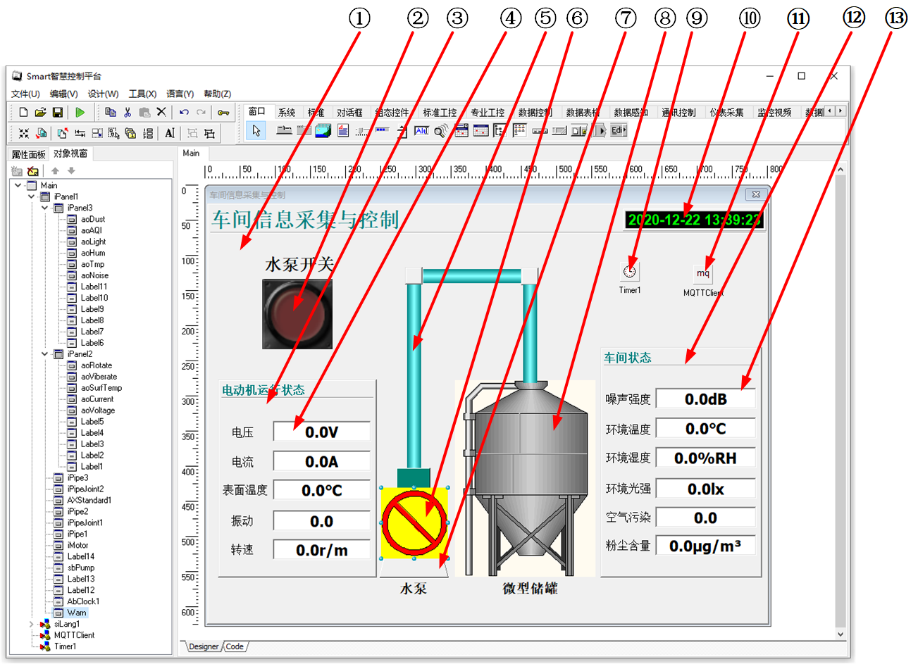
①:TiPanel组件,控件名称为iPanel1。
②:TSwitchButton组件,控件名称为sbPump。
③:TiPanel组件,控件名称为iPanel2。
④:TiAnalogOutput组件,控件名称从上到下依次为aoVoltage、aoCurrent、aoSurfTemp、aoViberate、aoRotate。
⑤:TiPipe组件,显示为绿色的管道,其控件名称从左至右为iPipe1、iPipe2、iPipe3。
⑥:TAXStandard组件,控件名称为Warn。
⑦:TiMotor组件,控件名称为iMotor。
⑧:TAXStandard组件,控件名称为AXStandard1。
⑨:TTimer组件,控件名称为Timer1。
⑩:TAbClock组件,控件名称为AbClock1。
(11):TMQTTClient组件,控件名称为MQTTClient1。
(12):TiPanel组件,控件名称为iPanel3。
(13):TiAnalogOutput组件,控件名称从上到下依次为aoNoise、aoTmp、aoHum、aoLight、aoAQI、aoDust。
Main窗体属性设置
Caption:主窗体标题,设置为车间信息采集与控制。ClientHeight:窗体客户区高度=600。ClientWidth:窗体客户区宽度=800。
①iPanel1属性设置
Height:设置控件显示高度,设置为600。Width:设置控件显示宽度,设置为800。TitleText:设置显示的标题,设置为车间信息采集与控制。
②sbPump属性设置
Height:设置控件显示的高度,设置为100。Width:设置控件显示的宽度,设置为100。SwitchOff:设置IsChecked=False时显示的图片。点击属性右侧的[...]按钮,打开文件上传界面,点击[Load...]从文件浏览器中选择对应的图片文件上传,返回该界面下,待显示出图片后点击[OK]加载图片。

SwitchOn:设置IsChecked=True时显示的图片。点击属性右侧的[...]按钮,打开文件上传界面,点击[Load...]从文件浏览器中选择对应的图片文件上传,返回该界面下,待显示出图片后点击[OK]加载图片。

③iPanel2属性设置
Height:设置控件显示高度,设置为282。Width:设置控件显示宽度,设置为226。TitleText:设置显示的标题,设置为电动机运行状态。
④aoVoltage,aoCurrent,aoSurfTemp,aoViberate,aoRotate属性设置
Height:设置控件高度,设置为30。Width:设置控件宽度,设置为140。UnitsText:设置显示的单位名称。aoVoltage此处设置为V。aoCurrent此处设置为A。aoSurfTemp此处设置为℃。aoRotate此处设置为r/m。
⑥Warn属性设置
- 使用鼠标右键单击该控件,在右键选项中选择
[编辑]按钮,打开图标选择器,在该选择器中选择如图所示的图标,点击[确定]以切换为对应的图标。

- 使用鼠标右键单击该控件,在右键选项中选择
⑦iMotor属性设置
- 使用鼠标右键点击该控件,在弹出的右键菜单选项中选择
[Edit],打开编辑器,按照图示中的样式设置,设置完成后点击[OK]按钮。

- 使用鼠标右键点击该控件,在弹出的右键菜单选项中选择
⑧AXStandard1属性设置
- 使用鼠标右键单击该控件,在右键选项中选择
[编辑]按钮,打开图标选择器,在该选择器中选择如图所示的图标,点击[确定]以切换为对应的图标。

- 使用鼠标右键单击该控件,在右键选项中选择
⑩AbClock1属性设置
ClockOption:设置时钟显示的类型,设置为coDateTime。
(11)MQTTClient1属性设置
BrokerHostName:设置连接的MQTT服务端的IP地址,设置为实际使用的MQTT服务端地址,例如设置为192.168.0.113。BrokerPort:设置连接的服务端口号,设置为1883。ClientID:设置连接到的客户端的名称,设置为SmartClient。Password:设置连接到的客户端使用的登录密码。Topic:设置订阅的主题名称,设置为Motor/#,该中订阅方式可以订阅位于Motor/下的所有主题信息。UserName:设置用户名称。
(12)iPanel3属性设置
Height:设置控件显示高度,设置为328。Width:设置控件显示宽度,设置为230。TitleText:设置显示的标题,设置为车间状态。
(13)aoNoise,aoTmp,aoHum,aoLight,aoAQI,aoDust属性设置
Height:设置控件高度,设置为30。Width:设置控件宽度,设置为144。UnitsText:设置显示的单位名称。aoNoise此处设置为dB。aoTmp此处设置为℃。aoHum此处设置为%RH。aoLight此处设置为lx。aoDust此处设置为μg/m^3。
# 7. 程序设计
# 7.1. 程序初始设置
该程序无初始设置。
# 7.2. 事件设置
- (11)MQTTClient1-OnPublishReceived事件
当接收来自于指定主题的订阅信息时,解析并显示。
procedure TMyHandler.MQTTClientPublishReceived;
begin
  if ATopic = 'Motor/noise' then
  begin
    FThis.aoNoise.Value := StrToFloat(APayload);
  end;
  if ATopic = 'Motor/voltage' then
  begin
    FThis.aoVoltage.Value := StrToFloat(APayload);
  end;
  if ATopic = 'Motor/current' then
  begin
    FThis.aoCurrent.Value := StrToFloat(APayload);
  end;
  if ATopic = 'Motor/surftemp' then
  begin
    FThis.aoSurfTemp.Value := StrToFloat(APayload);
    if (StrToFloat(APayload) > 70) and  (FThis.sbPump.Enabled = True) then
    begin
      FThis.sbPump.IsChecked := False;
      FThis.MQTTClient.PublishStr('Motor/power','0');
      FThis.sbPump.Enabled := False;
      FThis.Warn.Visible := True;
    end;
    if (StrToFloat(APayload) < 50) and  (FThis.sbPump.Enabled = False) then
    begin
      FThis.sbPump.Enabled := True;
      FThis.Warn.Visible := False;
    end;
  end;
  if ATopic = 'Motor/light' then
  begin
    FThis.aoLight.Value := StrToFloat(APayload);
  end;
  if ATopic = 'Motor/viberate' then
  begin
    FThis.aoViberate.Value := StrToFloat(APayload);
  end;
  if ATopic = 'Motor/rotation' then
  begin
    if APayload = '-60' then
      FThis.aoRotate.Value := 0
    else
      FThis.aoRotate.Value := StrToFloat(APayload);
  end;
  if ATopic = 'Motor/dust' then
  begin
    FThis.aoDust.Value := StrToFloat(APayload);
  end;
  if ATopic = 'Motor/AQI' then
  begin
    FThis.aoAQI.Value := StrToFloat(APayload);
  end;
  if ATopic = 'Motor/tmp' then
  begin
    FThis.aoTmp.Value := StrToFloat(APayload);
  end;
  if ATopic = 'Motor/hum' then
  begin
    FThis.aoHum.Value := StrToFloat(APayload);
  end;
  if ATopic = 'Motor/power' then
  begin
    if APayload = '1' then
    begin
      FThis.iMotor.FanOn := True;
      FThis.iPipe1.FlowOn := True;
      FThis.iPipe2.FlowOn := True;
      FThis.iPipe3.FlowOn := True;
    end
    else
    begin
      FThis.iMotor.FanOn := False;
      FThis.iPipe1.FlowOn := False;
      FThis.iPipe2.FlowOn := False;
      FThis.iPipe3.FlowOn := False;
    end;
  end;
end;
2
3
4
5
6
7
8
9
10
11
12
13
14
15
16
17
18
19
20
21
22
23
24
25
26
27
28
29
30
31
32
33
34
35
36
37
38
39
40
41
42
43
44
45
46
47
48
49
50
51
52
53
54
55
56
57
58
59
60
61
62
63
64
65
66
67
68
69
70
71
72
73
74
75
76
77
78
79
- ②sbPump-OnSwitch事件
切换开关的状态时触发该事件,向Motor/power发送开关的信息。
procedure TMyHandler.sbPumpSwitch;
begin
  if FThis.sbPump.IsChecked then
  begin
    FThis.MQTTClient.PublishStr('Motor/power','1');
  end
  else
  begin
    FThis.MQTTClient.PublishStr('Motor/power','0');
  end;
end;
2
3
4
5
6
7
8
9
10
11
- ⑨Timer1-OnTimer事件
定时器的触发事件,该事件仅会触发一次。用于初始化设备状态。
procedure TMyHandler.Timer1Timer;
begin
  FThis.Timer1.Enabled := False;
  FThis.MQTTClient.PublishStr('Motor/power','0');
end;
2
3
4
5
# 8. 运行结果
使用鼠标点击工具栏运行(Run),测试运行结果。
通过工具栏保存,将程序保存为 sdb 项目文件。
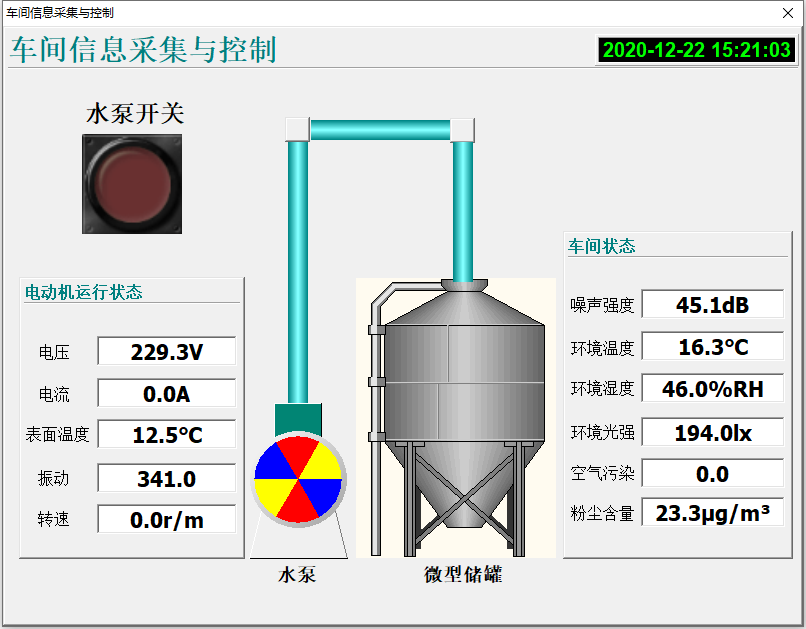
当程序启动后,电动机运行状态与车间状态处显示对应的采集数据信息,点击水泵开关处的开关,指示灯亮,对应的状态信息会发生相应的变化。