 ModbusTCP读取温湿度
# Smart之ModbusTCP读取温湿度
# 1. 说明
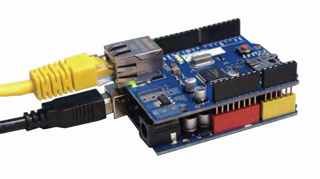
范例采用Modbus TCP通讯协议,读取驳接在Arduino上的DHT22温湿度传感器的数据。Arduino开发板与Ethernet W5100网络扩展板的连接方式如下图所示。
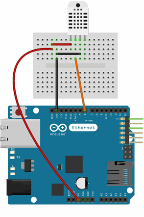
DHT22 是 DHT 系列的一款应用广泛的温湿度传感器。在范例中,DHT22温湿度模块的接线方式为正极接入W5100开发板的VCC(5V)引脚,负极接入W5100开发板的(GND)引脚,信号极(OUT)接入W5100开发板的8号引脚。DHT22的特性如下表所示。
| 名称 | 取值 |
|---|---|
| 工作电压 | 3V–5.5V |
| 温度测量范围 | -40℃–80℃ |
| 温度测量精度 | 0.5℃ |
| 湿度测量范围 | 0–100% RH |
| 湿度测量精度 | 2% RH |
通过范例学习,可以掌握ModbusTCP控件的基本设置,并结合Arduino开发板进行DHT22温湿度传感器的数据采集。
# 2. 零件连接图
# 3. 使用零件
| 序 | 零件名称 | 数量 |
|---|---|---|
| 1 | Arduino UNO R3 开发板 | 1 |
| 2 | Arduino Ethernet W5100 网络扩展板 | 1 |
| 3 | DHT22温湿度 模块 | 1 |
| 4 | USB数据线 | 1 |
| 5 | 面包板 | 1 |
| 6 | 杜邦线 | 3 |
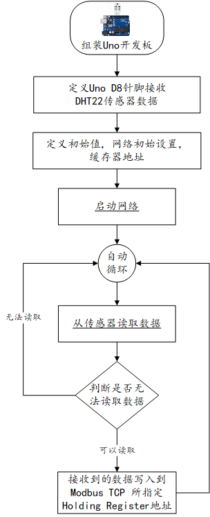
# 4. Arduino流程图
# 5. Arduino程序
使用Arduino IDE 编译并上传以下Arduino程序。
// 使用温湿度传感器之链接库 https://github.com/adafruit/DHT-sensor-library
// 采用 MyArduinoProjects Modbus TCP 链接库 http://myarduinoprojects.com/modbus.html
// 读取温湿度 因为Modbus无法传递小数字  所以先乘100到客户端取用时要除100

#include <DHT.h>
#include <SPI.h>
#include <Ethernet.h>
#include "MgsModbus.h"                                     // 引入Modbus TCP 链接库
MgsModbus Mb;

#define dhtPin 8                    //读取DHT22 Data
#define dhtType DHT22               //选用DHT22
DHT dht(dhtPin, dhtType); // Initialize DHT sensor

// 设置网络 (网络扩充卡 MAC 可自行修改 +1 避免冲突)
byte mac[] = {0x90, 0xA2, 0xDA, 0x0E, 0x94, 0xB8 };    //设置网络扩展卡的MAC地址
IPAddress ip(192, 168, 0, 164);                        //设置设备的IP地址
IPAddress gateway(192, 168, 0, 1);            //设置网关
IPAddress subnet(255, 255, 255, 0);            //设置子网掩码

void setup() {
   Serial.begin(9600);              //设定通信速率9600
   Ethernet.begin(mac, ip, gateway, subnet);               // 启动网络
   Serial.println("网络已经开通");

   //设置要使用的缓存器地址
   //0 1 2 3 4 是 Holding 缓存器的顺序,其地址分别是10000,10001,10002,10003,10004
   // 新增缓存器   mb.MbData(i);
   Mb.MbData[0] = 0;                                       // 地址 0 存放所测得之温度
   Mb.MbData[1] = 0;                                       // 地址 1 存放所测得之湿度
   dht.begin();//启动DHT
 }

void loop() {
   float h = dht.readHumidity()*100;                      //读取湿度 因为modbus 无法传递小数字  所以先乘100 到客户端取用时要除 100
   float t = dht.readTemperature()*100;                   //读取摄氏温度
   if (isnan(h) || isnan(t)) {
      Serial.println("无法从DHT传感器读取!");
      return;
   }
   Mb.MbData[0] = t;                                       // 地址 0 存放所测得之温度
   Mb.MbData[1] = h;                                       // 地址 1 存放所测得之湿度
   delay(500);                                             //延时 0.5 秒
   Mb.MbsRun();                                            //呼叫 Modbus
}
2
3
4
5
6
7
8
9
10
11
12
13
14
15
16
17
18
19
20
21
22
23
24
25
26
27
28
29
30
31
32
33
34
35
36
37
38
39
40
41
42
43
44
45
# 6. 设计明细
开启Smart智慧控制平台,分别加入下插图之控件。或者通过点击菜单栏[文件]-[打开项目]选择范例项目文件来打开该范例。

①:TModbusTCP组件,控件名称为ModbusTCPDHT22。
②:TImage组件,控件名称为Image1。
③:TShape组件,控件名称为Shape1。
④:TPanel组件,控件名称为Panel1。
⑤:TLabel组件,控件名称为Label9。
⑥:TPanel组件,控件名称为Panel2。
⑦:TLabel组件,控件名称为Label1。
⑧:TLabel组件,控件名称为Label3。
⑨:TLabel组件,控件名称为Label2。
⑩:TWidgetLCDLabel组件,控件名称为WidgetLCDLabel1。
(11):TLabel组件,控件名称为Label4。
(12):TTimer组件,控件名称为Timer1。
(13):TSwitchButton组件,控件名称为SwitchButton1。
(14):TLabel组件,控件名称为Label10。
(15):TLabel组件,控件名称为Label5。
(16):TLabel组件,控件名称为Label6。
(17):TWidgetLCDLabel组件,控件名称为WidgetLCDLabel2。
(18):TLabel组件,控件名称为Label7。
(19):TLabel组件,控件名称为Label8。
Main窗体属性设置
Caption:主窗体标题,设置为ModbusTCP读取温湿度。ClientHeight:窗体客户区高度=480。ClientWidth:窗体客户区宽度=720。
①ModBusTCPDHT22属性设置
AutoConnect:设置自动连接=True。Host:设置ModbusTCP设备的IP地址,此处设置需与Arduino中设置的IP地址一致,例如可设置为192.168.1.162。Name:控件名称,设置为ModbusTCPDHT22。Port:ModbusTCP设备使用的端口。默认为502。
②Image1属性设置
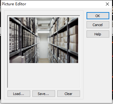
Stretch:设置图片拉伸=True。Height:设置图片高度=480。Width:设置图片宽度=720。Picture:设置显示背景图片。点击Picture属性右侧的[...]按钮,打开文件上传界面,点击[Load...]从文件浏览器中选择对应的图片文件上传,返回该界面下,待显示出图片后点击[OK]加载图片。
③Shape1属性设置
Height:设置控件高度=262。Shape:设置形状=stRoundRect(圆角矩形)。Width:设置控件宽度=544。
④Panel1属性设置
BevelInner:设置内斜边样式=bvRaised。BevelKind:设置斜边的样式=bkSoft。BorderStyle:设置边界的样式=bsSingle。Color:设置颜色=clBtnText。Height:设置控件高度=217。Width:设置控件宽度=500。
⑤Label9属性设置
Caption:设置标签文字,设置为开。Font:设置字体。设置内容如下图。

⑥Panel2属性设置
BevelInner:设置内斜边样式=bvRaised。BevelKind:设置斜边的样式=bkSoft。BorderStyle:设置边界的样式=bsSingle。Color:设置颜色=clMenuText。Height:设置控件高度=83。Width:设置控件宽度=404。
⑦Label1属性设置
Caption:设置标签文字,设置为串口读取温湿度。Font:设置字体。设置内容如下图。

⑧Label3属性设置
Caption:设置标签文字,设置为Temperature。Font:设置字体。设置内容如下图。

⑨Label2属性设置
Caption:设置标签文字,设置为温度。Font:设置字体。设置内容如下图。

⑩WidgetLCDLabel1属性设置
Caption.Format:显示格式,设置为00.00。Height:设置控件高度=60。Width:设置控件宽度=209。
(11)Label4属性设置
Caption:设置标签文字,设置为℃。Font:设置字体。设置内容如下图。
(12)Timer1属性设置
Enabled:启用计数器,设置为False。Interval:设置计数时间间隔(ms)=5000。
(13)SwitchButton1属性设置
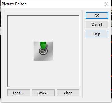
IsChecked:开关状态,设置为False。SwitchOff:关闭状态时显示的图片。点击SwitchOff属性右侧的[...]按钮,打开文件上传界面,点击[Load...]从文件浏览器中选择对应的图片文件上传,返回该界面下,待显示出图片后点击[OK]加载图片。

SwitchOn:打开状态时显示的图片。点击SwitchOn属性右侧的[...]按钮,打开文件上传界面,点击[Load...]从文件浏览器中选择对应的图片文件上传,返回该界面下,待显示出图片后点击[OK]加载图片。
Height:设置控件高度=72。Width:设置控件宽度=68。Stretch:图像是否随控件大小拉伸,设置为True。
(14)Label10属性设置
Caption:设置标签文字,设置为关。Font:设置字体。设置内容如下图。
(15)Label5属性设置
Caption:设置标签文字,设置为温度。Font:设置字体。设置内容如下图。
(16)Label6属性设置
Caption:设置标签文字,设置为Humidity。Font:设置字体。设置内容如下图。
(17)WidgetLCDLabel2属性设置
Caption.Format:显示格式,设置为00.00。Height:设置控件高度=60。Width:设置控件宽度=209。
(18)Label7属性设置
Caption:设置标签文字,设置为%。Font:设置字体。设置内容如下图。

(19)Label8属性设置
Caption:设置标签文字,设置为RH。Font:设置字体。设置内容如下图。
# 7. 程序设计
# 7.1. 程序初始设置
该程序无初始设置。
# 7.2. 事件设置
- (13)SwitchButton1-OnSwitch事件
SwitchButton1在点击时会切换开-关状态,即改变IsChecked属性的值,此时会触发OnSwitch事件,该事件可用于启用或禁用Timer1计时器。
procedure TMyHandler.SwitchButton1Switch;
begin
  FThis.Timer1.Enabled := FThis.SwitchButton1.IsChecked;
end;
2
3
4
- (12)Timer1-OnTimer事件
计时器触发OnTimer事件,通过ModbusTCP读取数据并显示。
procedure TMyHandler.Timer1Timer;
var
 FData: string;
 v:TStrings;
 t:string;
 h:string;
Begin
  v:=TStringlist.Create;
  v.Delimiter:=',';
  try
    FThis.ModbusTCPDHT22.ReadHoldingRegisters(1,2,FData);//读取温湿度
    v.CommaText := FData;
    t:=FloatToStr(StrToInt(v.Strings[0])*0.01); //温度
    h:=FloatToStr(StrToInt(v.Strings[1])*0.01); //湿度
    FThis.WidgetLCDLabel1.Caption.Value := StrToFloat(t);
    FThis.WidgetLCDLabel2.Caption.Value := StrToFloat(h);
  Finally
   v.Free;
  End;
End;
2
3
4
5
6
7
8
9
10
11
12
13
14
15
16
17
18
19
20
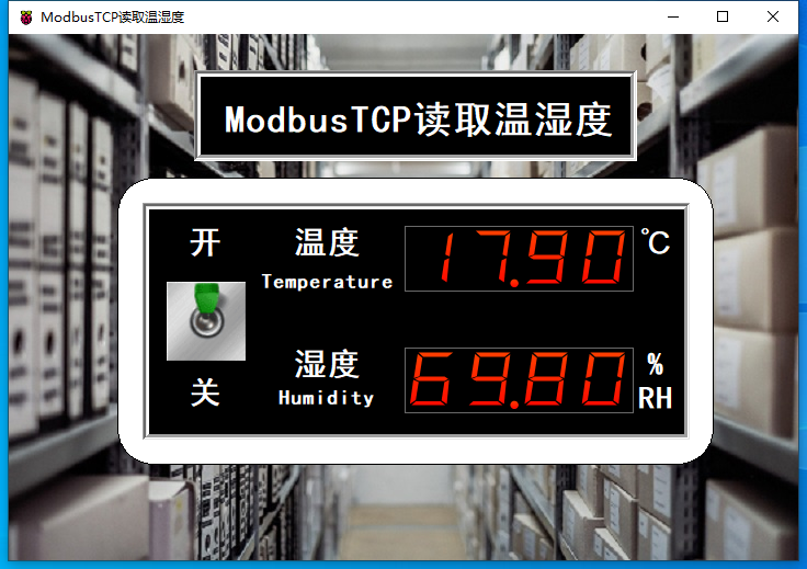
# 8. 运行结果
通过工具栏保存,将程序保存为 sdb 项目文件。
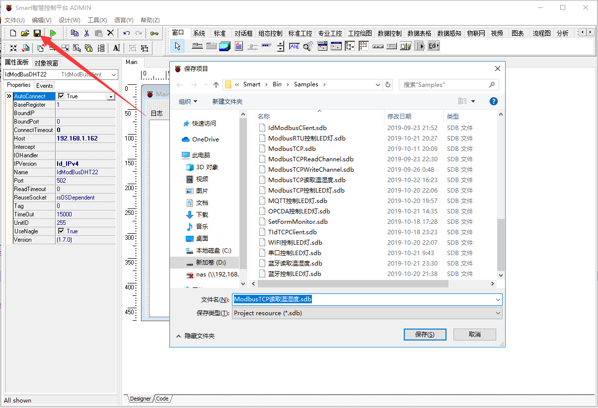
使用鼠标点击工具栏运行(Run),测试运行结果。测试运行结果。将图中的拨杆拨向“开”,数值显示屏中的温湿度数据每隔五秒更新一次。