 ModbusTCP读取温湿度
# PinToo之ModbusTCP读取温湿度
# 1. 说明
范例采用Modbus TCP通讯协议,读取驳接在Arduino上的DHT22温湿度传感器的数据。Arduino开发板与Ethernet W5100网络扩展板的连接方式如下图所示。
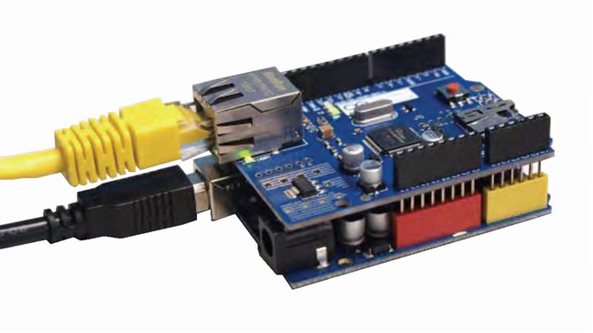
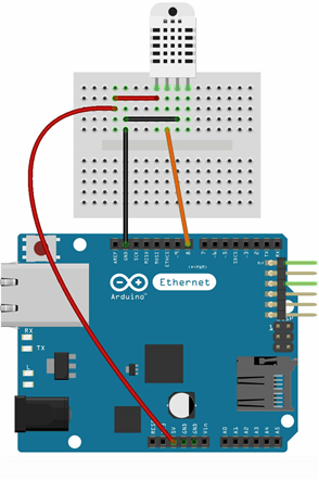
DHT22 是 DHT 系列的一款应用广泛的温湿度传感器。在本范例中,DHT22温湿度模块的接线方式为正极接入W5100开发板的VCC(5V)引脚,负极接入W5100开发板的(GND)引脚,信号极(OUT)接入W5100开发板的8号引脚。DHT22的特性如下表所示。
| 名称 | 取值 |
|---|---|
| 工作电压 | 3V–5.5V |
| 温度测量范围 | -40℃–80℃ |
| 温度测量精度 | 0.5℃ |
| 湿度测量范围 | 0–100% RH |
| 湿度测量精度 | 2% RH |
通过范例学习,可以掌握fxModbusTCP控件的基本设置,并结合Arduino开发板进行DHT22温湿度传感器的数据采集。
# 2. 零件连接图
# 3. 使用零件
| 序 | 零件名称 | 数量 |
|---|---|---|
| 1 | Arduino UNO R3 开发板 | 1 |
| 2 | Arduino Ethernet W5100 网络扩展板 | 1 |
| 3 | DHT22温湿度 模块 | 1 |
| 4 | USB数据线 | 1 |
| 5 | 面包板 | 1 |
| 6 | 杜邦线 | 3 |
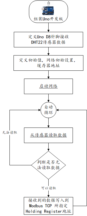
# 4. Arduino流程图
# 5. Arduino程序
使用Arduino IDE 编译并上传以下Arduino程序。
// 使用温湿度传感器之链接库 https://github.com/adafruit/DHT-sensor-library
// 采用 MyArduinoProjects Modbus TCP 链接库 http://myarduinoprojects.com/modbus.html
// 读取温湿度 因为Modbus无法传递小数字  所以先乘100到客户端取用时要除100

#include <DHT.h>
#include <SPI.h>
#include <Ethernet.h>
#include "MgsModbus.h"                                     // 引入Modbus TCP 链接库
MgsModbus Mb;

#define dhtPin 8                    //读取DHT22 Data
#define dhtType DHT22               //选用DHT22
DHT dht(dhtPin, dhtType); // Initialize DHT sensor

// 设置网络 (网络扩充卡 MAC 可自行修改 +1 避免冲突)
byte mac[] = {0x90, 0xA2, 0xDA, 0x0E, 0x94, 0xB8 };    //设置网络扩展卡的MAC地址
IPAddress ip(192, 168, 0, 164);                        //设置设备的IP地址
IPAddress gateway(192, 168, 0, 1);            //设置网关
IPAddress subnet(255, 255, 255, 0);            //设置子网掩码

void setup() {
   Serial.begin(9600);              //设定通信速率9600
   Ethernet.begin(mac, ip, gateway, subnet);               // 启动网络
   Serial.println("网络已经开通");

   //设置要使用的缓存器地址
   //0 1 2 3 4 是 Holding 缓存器的顺序,其地址分别是10000,10001,10002,10003,10004
   // 新增缓存器   mb.MbData(i);
   Mb.MbData[0] = 0;                                       // 地址 0 存放所测得之温度
   Mb.MbData[1] = 0;                                       // 地址 1 存放所测得之湿度
   dht.begin();//启动DHT
 }

void loop() {
   float h = dht.readHumidity()*100;                      //读取湿度 因为modbus 无法传递小数字  所以先乘100 到客户端取用时要除 100
   float t = dht.readTemperature()*100;                   //读取摄氏温度
   if (isnan(h) || isnan(t)) {
      Serial.println("无法从DHT传感器读取!");
      return;
   }
   Mb.MbData[0] = t;                                       // 地址 0 存放所测得之温度
   Mb.MbData[1] = h;                                       // 地址 1 存放所测得之湿度
   delay(500);                                             //延时 0.5 秒
   Mb.MbsRun();                                            //呼叫 Modbus
}
2
3
4
5
6
7
8
9
10
11
12
13
14
15
16
17
18
19
20
21
22
23
24
25
26
27
28
29
30
31
32
33
34
35
36
37
38
39
40
41
42
43
44
45
# 6. 设计明细
开启PinToo设计器,分别加入下插图之控件。或者点击左上角的[打开模板Lib文件]选择模板文件来打开对应模板。
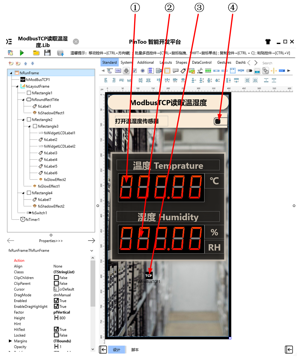
①:TfxWidgetLCDLabel组件,控件名称为fxWidgetLCDLabel1。
②:TfxWidgetLCDLabel组件,控件名称为fxWidgetLCDLabel2。
③:TfxModbusTCP组件,控件名称为fxModbusTCP1。
④:TfxSwitch组件,控件名称为fxSwitch1。
fxRunFrame属性设置
Height:设置页面高度=800。Width:设置页面宽度=400。
fxTimer1属性设置
Interval:设置计时器触发的时间间隔,单位为ms,设置为5000。Enabled:设置是否启用,设置为False。
①fxWidgetLCDLabel1属性设置
Height:设置控件高度=95。Width:设置控件宽度=285。Color:设置背景颜色=Black。
②fxWidgetLCDLabel2属性设置
Height:设置控件高度=95。Width:设置控件宽度=285。Color:设置背景颜色=Black。
③fxModbusTCP1属性设置
AutoConnect:是否在程序启动后启用ModbusTCP连接,设置为True。Host:设置连接的Modbus设备的IP地址,此处需设置为在Arduino程序中指定的设备IP地址,例如192.168.0.164。
# 7. 程序设计
点击程序设计界面右下角的按钮,切换至单元选择界面,勾选需要使用的单元。该程序需引用uModbusTCP单元。
# 7.1. 程序初始化设置
在程序启动时,对显示屏的样式进行格式化操作。
Begin
  fxWidgetLCDLabel1.Caption.FillOff.Color := NULL;
  fxWidgetLCDLabel2.Caption.FillOff.Color := NULL;
  fxWidgetLCDLabel1.Caption.Format := '000.00';
  fxWidgetLCDLabel2.Caption.Format := '000.00';
End.
2
3
4
5
6
# 7.2. 事件设置
- ④fxSwitch1-OnSwitch事件
点击切换以开启或者关闭计时器。
Procedure fxSwitch1OnSwitch(Sender: TObject);
//开启、关闭温湿度读取
Begin
  fxTimer1.Enabled := fxSwitch1.IsChecked;
End;
2
3
4
5
- fxTimer1-OnTimer事件
计时器定时触发事件,开启后每隔一定时间读取数值并显示。
Procedure fxTimer1OnTimer(Sender: TObject);
//计时器定时读取温湿度
var
 FData: String;
 v: TStrings;
 t:string;
 h:string;
Begin
  v := TStringList.Create;
  v.Delimiter := ',';
  try
    fxModbusTCP1.ReadHoldingRegisters(1,2,FData); //读取温湿度
    v.CommaText := FData;
    t:=FloatToStr(StrToInt(v.Strings[0])*0.01); //温度
    h:=FloatToStr(StrToInt(v.Strings[1])*0.01); //湿度
    fxWidgetLCDLabel1.Caption.Value := StrToFloat(t);
    fxWidgetLCDLabel2.Caption.Value := StrToFloat(h);
  Finally
    v.Free;
  End;
End;
2
3
4
5
6
7
8
9
10
11
12
13
14
15
16
17
18
19
20
21
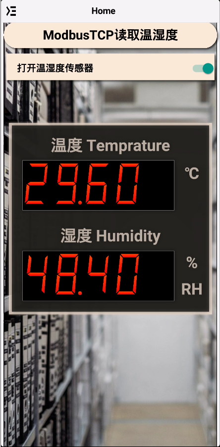
# 8. 运行结果
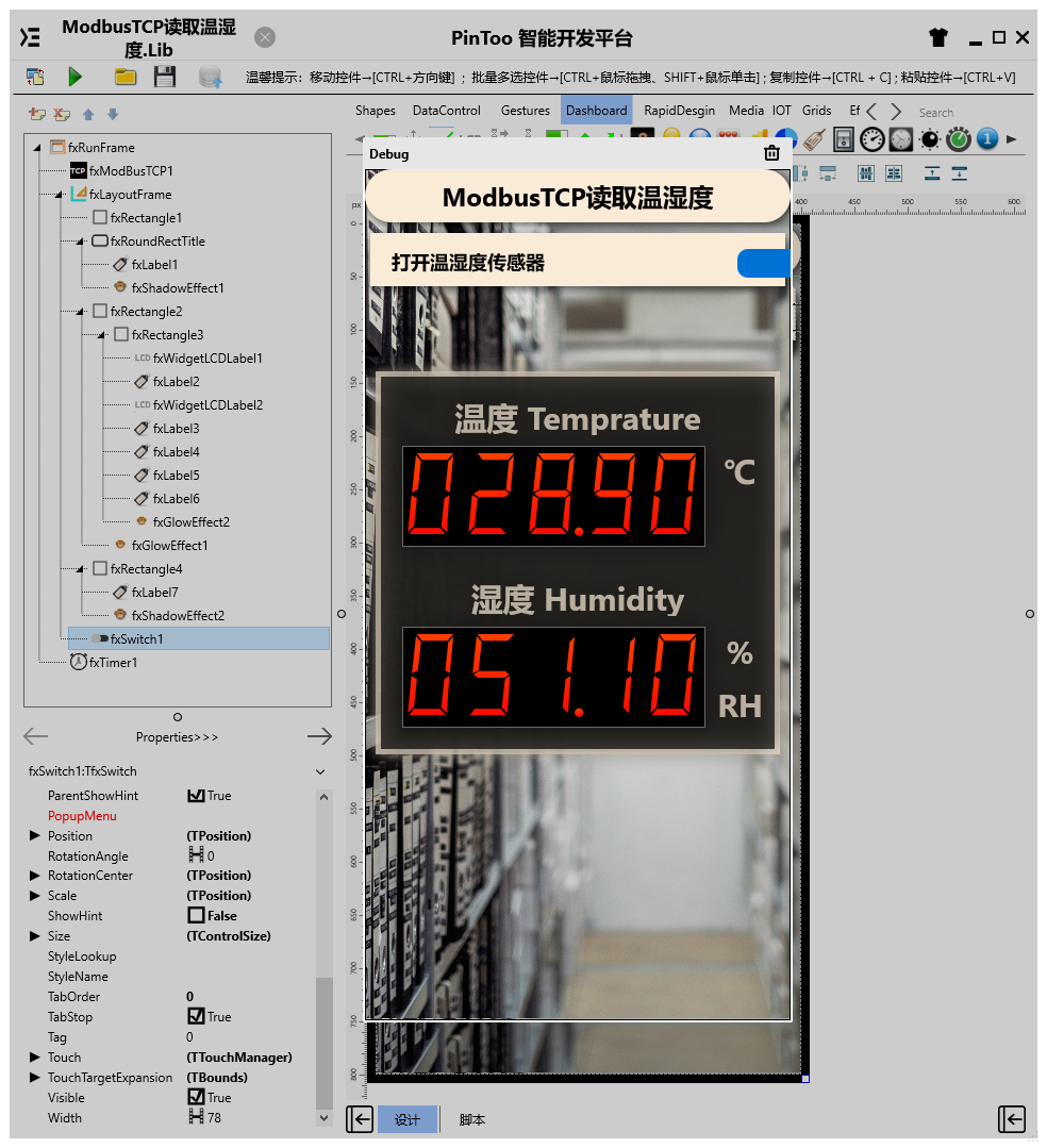
使用鼠标在 PinToo 菜单,点击[保存至数据库]按钮,将其保存至数据库,点击[调试运行]确认能够正常打开。
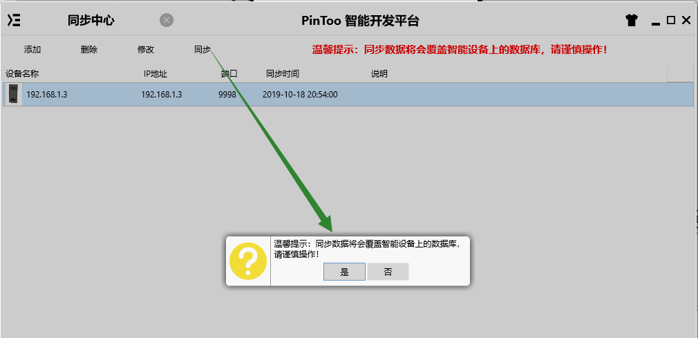
通过同步中心,将程序上传至手机PinToo运行;同步时,请确保手机已经运行PinToo,并且已经登陆。
在手机上运行该范例,点击打开温湿度传感器的开关,每隔五秒钟读取温湿度数据并显示在屏幕上。